Cylinder Head Valve Train Components and related parts
Engine Fix UK can provide the complete range of components to enable repair, refurbishment and reconditioning of the cylinder head and related parts. Our range is comprehensive and covers most Vintage, Classic and Modern Tractors and Agricultural equipment, additionally we cover all on and off–highway, marine and power generation applications.

Cummins 4BT Cylinder Head
We are able to supply the following parts:
- Cylinder Head either the bare head or the fully assembled head
- Intake and exhaust valves
- Valve collets/Keepers & Valve retainers
- Inner/Outer Valve springs
- Valve Guides
- Valve stem seals
- Core plugs
- Valve seats
In addition we also offer the parts that actuate the valves namely:
- Rocker Lever Assemblies including lever, pedestals and shafts
- Push Rods
- Tappets
- Camshafts
- Camshaft bush kits
The function of the valve train components is to provide a cyclic supply of fresh air and the exhaust air during combustion must be removed. The Cylinder control devices (Inlet and Outlet ports) are periodically opened and closed by shut-off devices ( Intake and Exhaust Valves), the valves fulfill the following tasks.
- Clear the largest possible opening diameter
- Perform opening and closing process rapidly
- Have a streamlined shape to avoid pressure loss
- Perform effective sealing when closed
- Provide advanced durability characteristics.
The valve train by its nature is subjected to high acceleration and deceleration speeds, as the engine accelerates the resulting inertia forces also increase applying high stress to the valve components. Additionally the exhaust valve must be designed to withstand high temperatures resulting from the hot exhaust gases, in order to operate reliably in this harsh environment valve train components must satisfy the following criteria.
- Provide advanced durability resistance over the entire life of the engine
- Ensure friction free operation
- Provide good heat removal capacity of the valves
Design Criteria
Intake valves typically operate at temperatures of 650 DEG C, however in turbocharged engines that can be up to 700 DEG C. Exhaust valves typically operate at temperatures of about 800-850 DEG C. The maximum temperature in valves is often not at the head, but in the centre of the valve at the fillet radius. The contact angle and width between the valve face and seat must be sufficient to allow sealing of the combustion pressures and gases and the dissipation of heat from the valve head to the valve seat and the cylinder head.
It is estimated that 75% of the heat in a valve is dissipated through the valve seat and 25% through the stem to the valve guide. Both the inlet and exhaust valves receive some cooling from the airflow entering the cylinder during the induction stroke , however the inlet valve receives more cooling , while the exhaust valve is heated more by exhausting the combustion gases. Poor contact between the valve face and the valve seat can result in the valve running several hundred degrees hotter, shortening the valve life.
Valve Materials
The material selected for a valve must a wide range of properties. Valves must maintain a high hardness at elevated temperatures to withstand the forces generated when hard particles become trapped between the valve face and seat. Both the valve head and stem must be strong enough to withstand the seating forces at high engine speeds and temperature. It must have good thermal fatigue properties, it must withstand stem, face and tip wear and high temperature corrosion. The valve tip must be able to withstand the high loads generated whilst opening the valve, especially for exhaust valves opening against the high cylinder combustion pressures.
Exhaust valves are typically made of austenitic, nitrogen bearing chrome nickel alloys possessing high temperature strength, hardness and corrosion resistance to combustion products, Inconel is another superalloy that is often used in exhaust valves where there are very high temperatures, its use is growing amongst turbo and supercharged applications. Stellite facing alloys are being used in high heat, high combustion applications such as CNG, Marine and Turbo diesel applications.
In later applications, exhaust materials are being used with facing alloys on the intake valves. New Exhaust Gas Recirculation (EGR) requirements on heavy duty engines have driven this due to excessive heat, new low sulfur diesel and changes to fluids and oils in use.

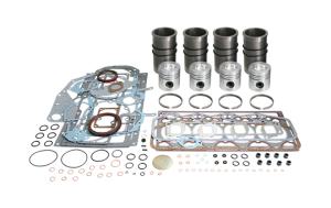
Valve Train Kit
On the inlet or intake side traditional materials are still being used with normally aspirated engines and some turbo applications, these alloys are typically Silchrome 1 and 8645H. For later models or high performance engines, the intake valves are manufactured out of Silchrome with a 8,5 percent chromium content. However the type of material specified very much depends on the engine application and running temperatures so the materials used start with low alloy steels Sil to medium –alloy steels (21-2N, 21-4N, 23-8N) and superalloy steels with high nickel content(Inconel, Nimonic), further developments include proprietary compositions of nickel chrome, molybdenum etc.
The material for an inlet valve is a martensitic, magnetic material that has standard hardness of 26-28 HRC, the valve tip can be heat treated to produce a hardness of 50-59HRC, in Turbocharged engines the inlet valve will often be stellite faced. Stellite facing gives a face hardness of about 55-59HRC, has excellent corrosion resistance and can withstand heavy valve spring pressures.
Typical Inlet valve materials have a tensile strength of 62kg/mm2at 500 DEG C, 43 kg/mm2 at 600 DEG , 22 kg/mm2 at 700 DEG and 10 kg/mm2 at 800 DEG.
Based on these tensiles, inlet valves will fail at temperatures much over 600 DEG.
The material for the exhaust valve is an austenitic, non-magnetic material that has a standard hardness of 38-45HRC, generally heat treatment of this material is not possible therefore it has become very common for manufacturers to friction weld a different stem material to the head, leading to a bi-metallic valve, this allows hardening of the tip by heat treatment. However it is now common to make the entire valve out of a material of tensile strength 75 kg/mm2 at 500 DEG C and either wafer tip or stellite weld the tip, this produces a tip hardness of 50-59HRC, with increase in operating temperature the tensile strength reduces to 68 kg/mm2 at 600C, 58 kg/mm2 at 700C, 40 kg /mm2 at 800C and 34kg/mm2 at 900C.
To improve the properties of the valve stem, manufacturers opt either for nitriding (tufftriding) or chrome plating. Both processes increase hardness, significantly improve wear and seizure resistance, improve fatigue resistance, and increase resistance to corrosion and pitting. In general nitriding is harder (approx. 60HRC), thinner, less expensive, more environmentally friendly and has a slightly rougher finish. The nitriding process results in a surface layer of iron oxide and leaves the entire valve with a dark grey/black appearance. The surface hardness doubles that of the base material, but is only 10 to 20 microns thick. Hard chroming is a slighter softer finish (55HRC approx.), thicker, more expensive and environmentally unfriendly but produces a smoother finish. Hard chroming is usually the choice for higher revving engines running with smaller valve guide clearances and higher valve speeds.
Valve Failure Modes
A Failure due to Fatigue
Engine valves are subjected to repeated cyclic loading due to valve train dynamics, repeated loading results in materials falling well below the yield strength, when the material is subjected to fatigue, one or more cracks usually start developing in the material, and these propagate until complete failure occurs. There are different types of fatigue mechanisms:
- Thermal Fatigue
- High Cycle Fatigue
- Low Cycle Fatigue
- Surface Fatigue
- Bending Fatigue
- Corrosion Fatigue
- Torsional Fatigue
- Fretting fatigue
In valves the most common failures are due to thermal, corrosion, low and high cycle fatigue.
Failure due to High Temperature
Exhaust valves operate at very high temperatures and are subject to cyclic loading, the failure of the conical surface of the valve is generally caused by the elastic and plastic deformation, and fatigue. Exhaust valve stem generally fail by overheating because the temperature of the exhaust valve is 720 degrees C. The fracture surface of the valve stem is covered with a black oxide scale, fracture surface in the fatigue area is smooth and is covered with thick oxide or deposits that cannot be removed, In the middle portion of the stem longitudinal fretting damage will have occurred. Some small cracks are initiated and propagated across the section. With high loading, multiple cracks are initiated if the valves are subjected to high temperatures and, under these operating conditions failure is expected to occur within a few million cycles.
Failure of valve due to erosion-corrosion
Due to high operating temperatures, the resulting scale formation on the valves corrodes the surface of the valve due to exhaust flue gases. Structural metals have always had surface material removed in service as the result of erosion by small, solid, impacting particles. The erosion–corrosion of exhaust valves of exhaust valves (valve guttering) is an important cause of failure of internal combustion engine valves. Valve guttering is generally caused by the exhaust gas flowing across the valve face surface, resulting in the formation of a radial channel or gutter.
Typical causes of valve leakage include valve distortion, face peening and degradation of face deposits. The accumulation of combustion-derived deposits on valve surfaces interferes with proper seating of the valve and leads to leakage.
Failure of Valve due to Wear
Occurs generally at the seating face of valves and stem that slide on the valve stem guide. Wear occurs due to two primary factors:
- Impact Force between seating face of valve and seat insert.
- Sliding of the Valve on the seat insert during the action of combustion pressure.
The rubbing action and impacting action wear out the valve face, the wear mechanisms include adhesive, abrasive, fretting, erosion, cavitation and contact rolling fatigue.
Valve Guide Materials
Cast Iron is still widely used, although the material composition has become proprietary in order to combat wear, also powdered metal are also becoming widely used.
Valve Spring Materials
The modern day requirement of diesel engines requires the use of Silicon Chrome alloy steel wire springs to ensure high tensile strength suitable for high dynamic applications. This material has a higher resistance to fatigue and relaxation at elevated temperatures when compared to carbon steels. Valve springs typically operate in working temperatures of 200 + Degrees C. The springs used are made from superclean raw rod to ensure freedom from impurities and non-metallic inclusions leading to a high fatigue life.
Springs can be treated to obtain low friction and high corrosion resistance properties including:
- Wax/Oil Coating
- Nitriding
- Phosphating
- Shot Peening
- Spherodising
Nitriding is typically used in the highest stress applications, Nitriding in combination with shot peening allows the fatigue life to be improved further. Shot peening involves impacting he spring wire surface with high speed round metallic shot deforming or ‘ball peening‘ the surface to give a compressive residual stress layer that is resistant to crack propagation.


 Just Template IT